Those familiar with light water reactor (LWR) power plant design will recall that the containment building is the third and final line of defense (behind the fuel cladding and the reactor coolant pressure boundary) for radionuclide release. The containment is a pressure retaining, low leakage structure with prescriptive design requirements. A typical containment structure sits on a thick concrete and rebar foundation with steel reinforced concrete walls and an interior steel liner plate. The containment building is part of a defense-in-depth approach to protect plant and public safety.
Advanced, non-light water reactor designs introduce the idea of confinement (as opposed to containment) and apply the concept of a functional containment. A functional containment is defined in Reg Guide 1.232 as “a barrier, or set of barriers taken together, that effectively limit the physical transport and release of radionuclides to the environment across a full range of normal operating conditions, anticipated operational occurrences, and accident conditions.” The multiple barriers may be internal and/or external to the reactor and its cooling system and are provided to control the release of radioactivity to the environment and to ensure that the functional containment design conditions important to safety are not exceeded for as long as postulated accident conditions require.
In current LWR designs, the principal barrier to radionuclide release credited during severe accidents is the containment building. The limiting licensing basis event for the LWR is the loss-of-coolant accident resulting from a breach of the reactor coolant system. This postulated accident sequence is a rapid transient characterized by high energy release of high temperature, pressurized-water reactor coolant into the containment, which is assumed to result in significant damage to the oxide fuel pellets and zirconium cladding, followed later by hydrogen generation from fuel clad/steam interaction and potential hydrogen detonation. Since the initiating event is a breech in the reactor coolant circuit, it is assumed that the fuel cladding and reactor coolant pressure boundary are compromised. Thus, the containment building is required to absorb the stored energy of the coolant system, to absorb the energy of potential detonation of hydrogen, and to contain radionuclides released from the fuel, all reliant on the integrity of its design basis functions of pressure-retention and low-leak rates.
The functional containment approach limits radionuclide releases to the environment by emphasizing retention of radionuclides at their source in the fuel rather than allowing significant fuel particle failures and subsequent reliance upon other barriers (the reactor coolant system and containment building) to ensure that dose at the site boundary as a consequence of postulated accidents meets regulatory limits.
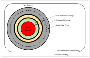
As an example, the functional containment in a modular high-temperature gas-cooled reactor (HGTR) utilizing spherical, Tri-Strcutural Isotropic (TRISO) fuel may be comprised of five barriers designed to limit radionuclide release from the core to the environment to insignificant levels during normal operation and across a broad spectrum of postulated accidents. Collectively, the TRISO fuel element or pebble comprises the first three release barriers (the fuel kernel, the fuel particle coatings, and the spherical fuel-element matrix, including the fuel-free zone) [See Fig. 1], which retain >99.999% of the fission products even during beyond design basis events (BDBEs). The fuel element functions as its own containment. The remaining two release barriers are the reactor helium pressure boundary and the reactor building. Additionally, a breach or failure of one pebble does not have an impact on any of the neighboring radionuclide barriers, whereas in the LWR design radionuclide barriers are interconnected.

Figure 1 – Example HTGR Radionuclide Retention System (Functional Containment)

